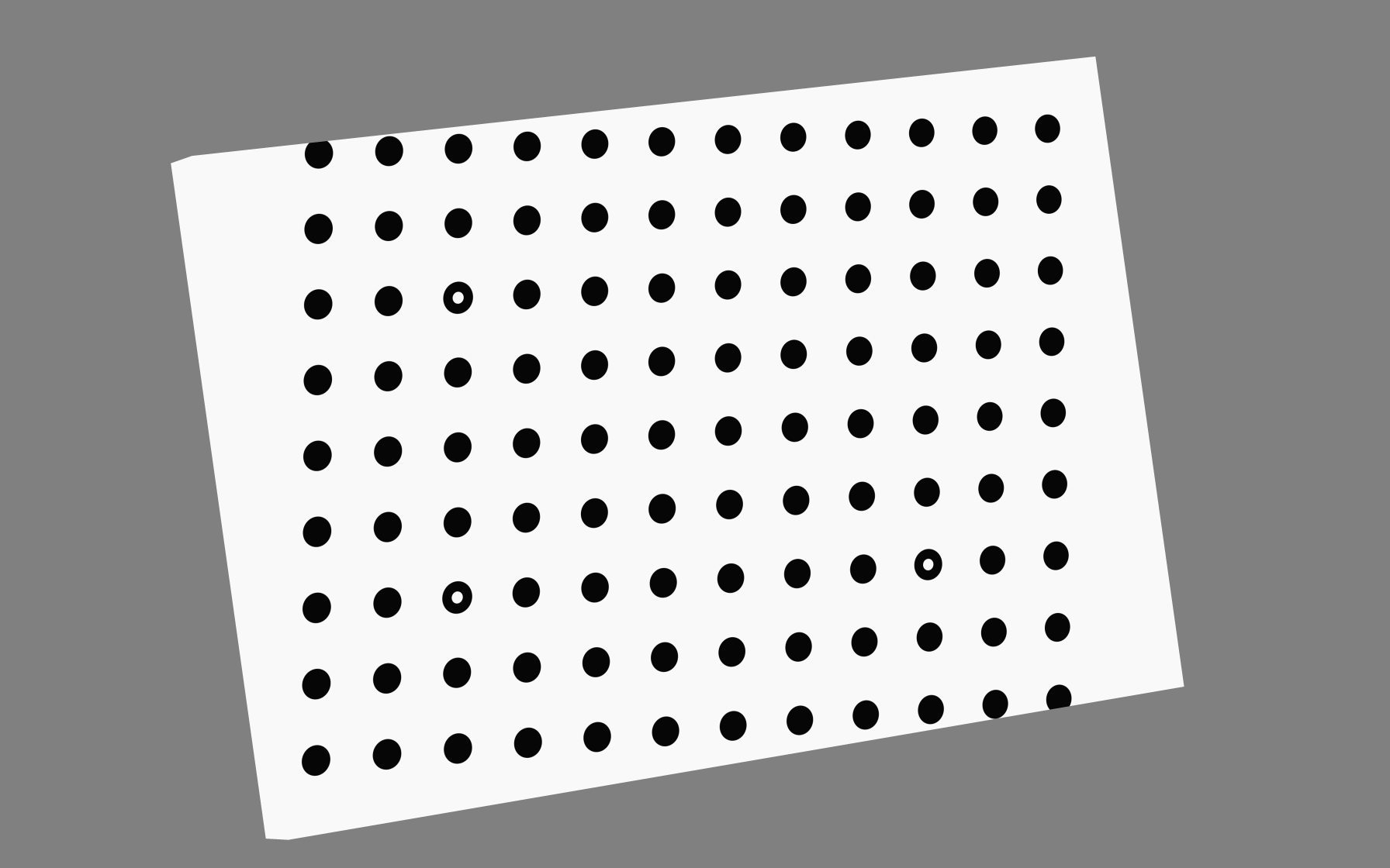
Note
Go to the end to download the full example code.
Render UVs: Texture aspect and fit modes
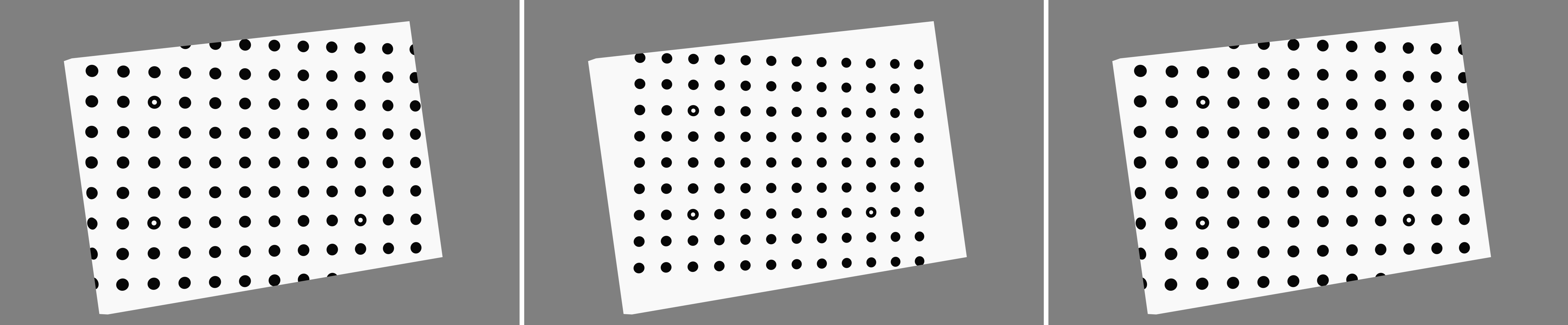
This example compares planar texture fitting when the mesh and UV axes are aligned, then repeats the comparison after rotating the mesh while leaving the UV axes fixed in the camera frame. This separates texture aspect effects from the effect of projecting an oblique target onto fixed UV axes.
1. Load the packaged three dimensional calibration plate
data_dir = dataset.riley_stereocal_case_path()
simulation = io.MeshLoader(
    load_dir=data_dir,
    coords_file="coords.csv",
    connect_files="connect.csv",
    load_opts=io.SimLoadOpts(coord_header=None),
).load_mesh()

base_mesh = render.meshes3d_from_simdata(
    simulation,
    {"connect": riley.ConnectConvention(
        riley.EElemType.TRI3, riley.EConnectAxis.ROW, 0,
        riley.ENodeOrder.RILEY,
    )},
)["connect"]

texture = riley.load_texture_mono_u8(dataset.riley_cal_target_texture_path())
2. Define the three aspect preserving fit modes
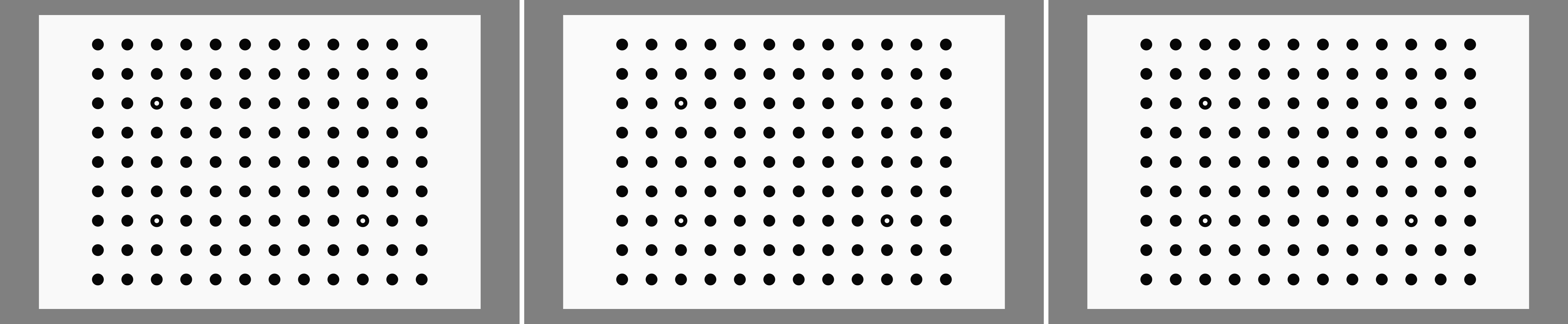
CONTAIN preserves the complete projected target while respecting the
texture aspect ratio. FIT_U spans the texture width and derives V from
the same scale; FIT_V spans its height and derives U. The latter two can
therefore extend outside the unit texture square when the projection and
texture have different aspect ratios.
fit_modes = (
    ("contain", render.EUVFit.CONTAIN),
    ("fit_u", render.EUVFit.FIT_U),
    ("fit_v", render.EUVFit.FIT_V),
)
3. Build aligned and rotated target cases
The aligned plate lies in the camera XY plane, so its physical axes and the planar UV axes coincide. The rotated plate is oblique, but UV projection is still performed in world XY (the camera frame), making the axis mismatch visible in the calibration grid.
aligned_mesh = base_mesh
rotated_mesh = render.mesh_rotate(
    base_mesh,
    Rotation.from_euler("xyz", (0.0, 24.0, 8.0), degrees=True),
    pivot=render.mesh_center(base_mesh),
)
4. Render both three mode comparisons
output_dir = Path.cwd() / "pyvale-output" / "renderuvs_ex1b_uv_texture_aspect"

for orientation_name, mesh in (
    ("aligned", aligned_mesh),
    ("rotated", rotated_mesh),
):
    camera = render.Camera(
        pixels_num=np.array((1792, 1120)),
        pixels_size=np.array((5.5e-6, 5.5e-6)),
        pos_world=np.zeros(3),
        rot_world=Rotation.identity(),
        roi_cent_world=render.mesh_center(mesh),
        focal_length=35.0e-3,
        subsample=4,
    )
    camera = render.cam_frame_mesh(
        camera,
        mesh,
        fov_scale=render.cam_coverage_to_fov_scale(0.90),
    )

    for fit_name, fit_mode in fit_modes:
        uvs = render.uv_project_planar(
            mesh.coords,
            texture_shape=texture.shape[-2:],
            fit=fit_mode,
        )

        textured_mesh = render.Mesh3D(
            element_type=mesh.element_type,
            coords=mesh.coords,
            connectivity=mesh.connectivity,
            shader=riley.TextureShader(uvs=uvs, texture=texture),
        )

        render_uv_example(
            textured_mesh,
            camera,
            output_dir / orientation_name / fit_name,
        )
5. Compare with a physically specified calibration dot pitch
Unlike the automatic fit modes, this mapping fixes the experimental scale at
1.25 mm per dot pitch using the measured 177.1 texture pixels per pitch. Its
oblique XY projection slightly exceeds the source texture, so the default
SATURATE policy clips those UVs and emits an explicit warning.
texture_px_per_leng = render.uv_calc_texture_px_per_leng(
    texture_px_per_feature=177.1,
    feature_leng=1.25e-3,
)

physical_mapping = render.uv_map_planar_scaled(
    rotated_mesh.coords,
    texture[0],
    texture_px_per_leng,
)

physical_mesh = render.Mesh3D(
    element_type=rotated_mesh.element_type,
    coords=rotated_mesh.coords,
    connectivity=rotated_mesh.connectivity,
    shader=riley.TextureShader(
        uvs=physical_mapping.uvs,
        texture=physical_mapping.texture[None, :, :],
    ),
)

physical_camera = render.Camera(
    pixels_num=np.array((1792, 1120)),
    pixels_size=np.array((5.5e-6, 5.5e-6)),
    pos_world=np.zeros(3),
    rot_world=Rotation.identity(),
    roi_cent_world=render.mesh_center(rotated_mesh),
    focal_length=35.0e-3,
    subsample=4,
)

physical_camera = render.cam_frame_mesh(
    physical_camera,
    rotated_mesh,
    fov_scale=render.cam_coverage_to_fov_scale(0.90),
)

render_uv_example(
    physical_mesh,
    physical_camera,
    output_dir / "physical_pitch",
)

image_leng_per_px = render.cam_calc_leng_per_px(physical_camera)

image_px_per_feature_pitch = render.uv_calc_image_px_per_feature(
    1.25e-3,
    image_leng_per_px,
)

print(
    "Physical pitch mapping predicts "
    f"{image_px_per_feature_pitch:.2f} image px/dot pitch at the ROI"
)

print(f"Rendered UV fit variants to {output_dir}")
For the aligned target, contain, fit U, and fit V are shown from left to right. The target and UV axes coincide, so this row isolates the behaviour of the three aspect preserving fit policies.
The same contain, fit U, and fit V order is repeated after rotating the physical target. The UV projection axes remain fixed in the camera frame, so the grid now exposes the mismatch between target and UV axes.
Finally, the physically scaled mapping fixes the dot pitch instead of fitting the source image to either projected extent.